|
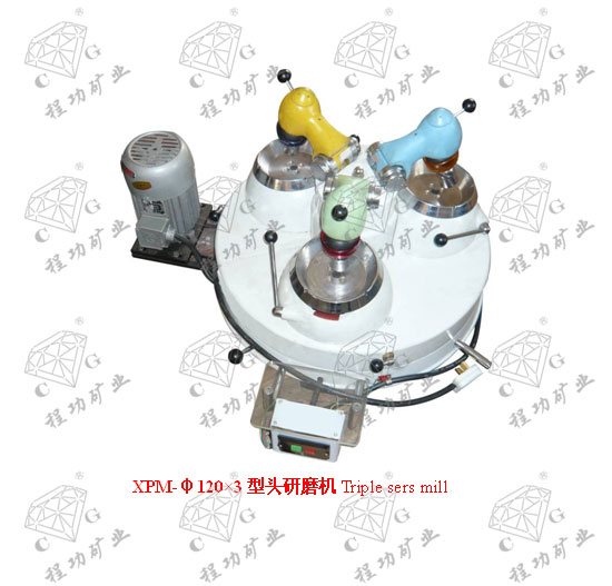
试验室XPM-Φ120×3型三头研磨机技术参数
Technical Parameter of laboratory triple sers mill
XPM-Φ120×3三头研磨机是一种干法磨细分析样品的研磨设备,主要供冶金、建材、化工、煤炭、水电、商检、地质等部门实验室磨细分析样品之用,也可以供有关方面作为磨细一般少量物料之用。
XPM-Φ120×3 triple sers mill is a kind of grinding equipment which mill and analyze samples through dry grinding. Such mills are mainly used to mill and analyze samples by laboratories in departments such as metallurgy, building material, chemical, coal, water and electricity, commercial inspection, and geology. They are also used to grind a small quantity of materials.
| 型号规格 Model |
单位Uite |
XPM-Φ120×3 |
| 研钵直径 Diameter |
mm |
Φ120 |
| 磨头数目 Amourt |
个 |
3 |
| 研棒转速 Speed |
r/min |
220 |
| 研钵转速 Speed |
r/min |
9 |
| 给料粒度 Feed size |
mm |
-1.5 |
| 产物粒度Size |
mm |
-0.074 |
| 每钵处理量Capacity |
g |
30 |
| 功率 Power |
w |
370 |
| 外形尺寸 Overall dimension |
mm |
780×750×500 |
| 质量 Weight |
kg |
105 |
三、主要结构说明
Main Structure
本机结构主要由三套磨头、离盒器、研钵支座、及定位器等总装组成。
The structure of such machine is as shown in Figure to Figure. See Figure for its overall structure which is mainly composed of three sets of grinding heads, clutch, mortar support, localizer, etc.
磨头、研体支座和离合器互成120°均匀地安装在转座上,转座的轴承中,在底座正面装有接料支板及电器,左方装有电机。当离合器接通时,电机通过皮带轮,齿轮轴,万向节带动磨头旋转。齿轮轴的另一头和研钵支座的齿轮啮合。由于研棒的正转和研钵的同向自转产生相对滑动,借磨头的自重产生压力磨细物料。
Grinding head, mortar support and clutch are evenly installed on the rotating seat and in the bearing of rotating seat, at an angle of 120°between each two of them. On the front of the base are mounted receiving support plate and electrical equipment; on its left is installed a motor. When the clutches are connected, the motor drives the rotation of the grinding head through the belt pulley, gear shaft, and cardan joint. The other end of gear shaft and the gear of mortar supportengage. Since relative sliding occurs due to clockwise rotation of grinding bar and clockwise rotation of mortar, the materials are grinded through the weight of grinding head.
离合器是常闭干式磨擦离合器。
See Figure for clutch which is normally closed dry friction clutch.
磨擦离合器的结合和脱开是靠杠杆绕支钉的上下摆动实现的,杠杆上抬时,弹簧被压缩,磨擦片与齿轮脱开。杠杆下移时,弹簧复位,磨擦片与齿轮端面贴面贴合,从而传递动力。
The matching and separation of friction clutch are realized through the up-and-down movement of lever around the support pin. When the lever is lifted up, the spring is compressed and the friction plate and gear are separated. When the lever is lowered down, the spring returns to its original position, and the friction plate matches the end face of gear so as to be able to transfer power.
杠杆的上下移动靠操纵手柄实现。手柄在图示右边时,离合器贴合,逆时针旋转到左边时,装在转盘里的轴靠偏心作用推动销子,顶起杠杆的调节螺丝,杠杆向上摆动,将离合器脱开。在使用过程中,当磨擦损时,可松开螺帽,向下调节调整螺丝。
The up and down movement of lever is realized through the control handle. When the handle is on the right as is shown in the figure, the clutches match and rotate to the left counterclockwise. The shaft in the rotating disk drives the dowel through eccentric action and jack up the adjusting screw of lever, the lever upswings and separates the clutch. In case of damage by rubbing during the application process, loosen the nuts and adjust the screws downward.
由于每一对研具都有单独的离合器操作,因此三对研具的运动互不影响,即可同时工作,也可使其中一对或二对工作。
As every pair of lapper is equipped with independent clutch, the three pairs of lappers move independently of each other. That is to say, all of them can operate simultaneously or operate in one pair and two pairs.
磨头结构见,当动力由离合器万向节传来时,由锥齿轮轴,锥齿轮带动轴旋转,由于偏心作用,轴带动轴承座及其上的研棒座,研棒绕轴作旋转运动。
See Figure for the structure of grinding head. When the power is transmitted from the cardan joint of clutch, the bevel gear shaft and bevel gear drive the rotation of shafts. Under eccentric action, the shafts drive the bearing pedestal and the grinding bar base above it. The grinding bar revolves around the shaft.
磨头压力的调节是靠调节盘簧的松紧来实现的。
The pressure of grinding head is adjusted through the adjustment of the tension of the coil spring.
由于旋转臂两侧装有两根轴,这两根轴分别装在轴承座的轴承上,固定在座盖,因此旋转臂可绕轴的轴心线旋转,为了调整磨头压力,在左右轴承座的外侧均装有一根盘簧它的一端上,另一端卡在轴上。当松开半园头螺钉,如果朝着研磨中心离开方向旋转盖,则盘簧收紧,磨头的压力可适当减少,反之,则磨头的压力可适当增加。用户可根据不同研磨对象自行调整,出厂时盘簧调整到减轻磨头压力的状态。
Since on the two sides of the rotary arm are two shafts which are installed on the bearings of bearing pedestal and fixed on the seat cover, the rotary arm can revolve around the axis line of shafts. To adjust the pressure of grinding head, on the outside of the left and right bearing pedestals coil spring is added to one end of it. The other end of it is clipped on the shaft If it moves toward the grinding center to leave the swiveling cover when the half round screws are loosened, the coil spring tightens up. The pressure of grinding pressure can be reduced properly. Otherwise, the pressure of grinding pressure can be increased properly. The user can adjust its pressure according to the grinding object. When it is ready for shipment, the coil spring shall be adjusted to the condition of reduced grinding head pressure.
研钵支座的结构,当动力由齿轮传来时,摩擦轮带动摩擦环,从而使研钵旋转。另外轴承座通过轴铰接于研钵支座横孔中,当抬起磨头,取下钵罩,操纵手柄,则研钵随同轴承座绕轴旋转,以便倒也已磨好的物料。
See Figure for the structure of mortar support. When the power is transmitted from the gear, the friction wheel drives the friction ring so as to get the mortar to rotate. In addition, the bearing pedestal is hinged to the cross-drilled holes of mortar support through shafts. When the grinding head is lifted up, and the mortar cover and the control handle are dismounted, the mortar revolves around the shaft along with the bearing pedestal (03-1), to handle the already grinded materials.
定位器的结构,轻轻按一下手柄套,轴承座从转盘的定位槽中退出,以便换位,当转盘转到所需位置时,轴承座嵌入转盘槽中实现换位。
See Figure for the structure of localizer. Press the handle sleeve gently and the bearing pedestal gets out of the locating slot of the rotating disk to change position. When the rotating disk rotates to the required position, the bearing pedestal is embedded into the locating slot of the rotation disk to realize change of position.
平时操作者一般坐在设备正面接料架处,操纵开关,离合器手柄和定位手柄即可对三对研具依次进行操作。
Generally, the operator sits on the receiving material shelf on the front of the equipment. The three pairs of lappers can be operated in sequence if the switch, clutch handle, and locating handle are controlled.
为了适应磨细多种物料的要求,三对研具间设有隔板,以防样品互相混杂。
To grind various kinds of materials, clapboards are installed among the three pairs of lappers to avoid mixing of samples.

| 
