|
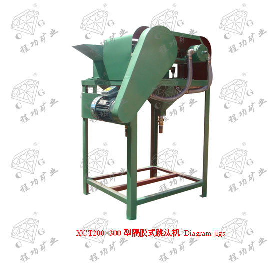
试验室XCT型隔膜式跳汰机技术参数
Technical Parameters of Laboratory XCT Diaphragm Jig
一、用途
Ⅰ.Use
XCT型隔膜式跳汰机用于重力选矿,重力选矿是基于矿石的比重不同,在介质中沉降速度亦异,利用矿物重量上的差别,而完成矿粒混合物的分层选别工作。本产品由原地矿部唯一指定企业生产,执行行业标准。
隔膜式跳汰机适于选别黑色和有色金属、化学、建筑等方面的实验研究之用。
XCT Diaphragm Jig is applied to gravity concentration, which makes layered separations of ore grain mixture using difference in mineral weight based on variation of settling speed for the different specific gravity of ores in medium. The product is made by the only manufacturer designated by the former Ministry of Geology and Mineral Resources, in compliance with the Industrial standards.
XCT Diaphragm Jig is suitable to used for research in labs of ferrous and non-ferrous metals, chemical, building materials and other industries.
二、技术参数
Ⅱ. Technical Parameters
| 型号规格 Model |
单位 Uite |
XCT100×150 |
XCT200×300 |
| 跳汰室长度 Length |
mm |
150 |
300 |
| 跳汰室宽度 Width |
mm |
100 |
200 |
| 跳汰室数 Jig chamber |
(个) |
2 |
2 |
| 跳汰室面积 Area |
m2 |
0.03 |
0.06 |
| 偏心****冲程 Stroke |
mm |
≤20 |
≤32 |
| 给矿粒度 Feed size |
mm |
≤3 |
≤6 |
| 每分钟冲次 Times of stroke |
1/min |
420 |
346 |
| 处理能力 Capacity |
kg/h |
20-70 |
≤700 |
| 筛下水的****量 Water comsumption |
L/S |
0.117 |
0.117 |
| 筛上水的****量Water comsumption |
L/S |
0.10 |
0.10 |
| 电机功率 Power |
kw |
0.4 |
0.75 |
| 外形尺寸Overall dimensions |
mm |
752×520×1312 |
1110×520×1312 |
| 重量 Weight |
kg |
150 |
175 |
三、结构原理
III. Structure and Working Principle
隔膜式跳汰机,如图一所示,它上部为长方形,而下部为角锥形的洗矿槽1与2,两个相连,装在机架3上构成一体,各槽各有跳汰区A、B和隔膜区C,在A、B两区之间用不到底的隔板分开。各槽共助于同一传动装置4,配水活瓣5,如图二所示,及补助水管6,跳汰区上部跳汰过程靠隔膜往复运动造成水的鼓动来进行矿物分选,隔膜下冲时,在筛板下面供给补助水,补助水用配水活瓣5来调节,活瓣5与隔膜7的动作是同步的,当隔膜下降时活瓣关闭,水不进入跳汰机中,但隔膜上升时,活瓣启开因此,减少了跳汰机内下降水流的作用。
As is shown in Figure 1, the top of the diaphragm jig is rectangular and the bottom of it is pyramid-shaped washing trough 1 and washing trough 2. These washing troughs are linked together and installed on frame 3 to become one. There are jigging area A, jigging area B, and diaphragm area C in each trough. Jigging area A and jigging area B are separated by a division plate that does not reach the bottom. Each trough serves the same one transmission device 4 and is equipped with water valve 5 as shown in Figure 2 as well as water pipe 6. The jigging process in the upper side of the jigging area causes the agitation of water through the reciprocating motion of the diaphragm, so as to realize mineral separation. When the diaphragm moves downward, it supply supplement water under the sieve plate. The supplement water is adjusted through the water valve 5. The water valve 5 and diaphragm 7 operate synchronously. When the diaphragm moves downward, the water valve is shut and water does not enter the jig. When the diaphragm moves upward, the water valve is opened. Therefore, the function of descending water current in the jig is reduced.
槽体是灰口铁铸造而成,隔膜7乃固定在槽体水平铁垫8上密封而不漏,隔膜借助于偏心连杆9、10及隔膜连杆11与杠杆12相连接,并由杠杆12获得往复运动,因而在工作室造成相应的鼓动,杠杆又与套在轴13上的偏心连杆相连接,轴14由电动机15,通过三角皮带16及皮带轮17代动。
The trough is cast by gray pig iron. The diaphragm 7 is fixed on the horizontal iron washer 8 of tank which is well sealed. The diaphragms are connected through the eccentric links 9 and 10 as well as diaphragm 11 and lever 12. They do reciprocating motion through lever 12. Therefore, corresponding agitation is caused in the working chamber. The lever is then connected with the eccentric link covered on the shaft 13. The shaft 14 is driven by motor 15 through V-belt 16 and belt pulley 17.
各室的高度不同而成阶梯形,原矿经给矿槽18送入跳汰室,基于矿物比重不同,被水驱动而分别排出,沉入下层的是比重大的矿物经过截门19胶管20(胶管长度需根据实际使用条件决定)进入排矿瓶21,在上层比重小的矿物沿溢流槽22流出。
Due to different heights of each working chamber, the raw ores are fed into the jigging room after passing the feeding trough. They are discharged out after driven by water due to different specific gravities of ores. The ores sinking into the lower layers have large specific gravities. They pass the stop valve 19 and rubber hose 20 (the length of rubber hose depends on the actual service conditions) and then enter the ore discharging bottle 21. The ores at the upper layer with small specific gravity flow out along the overflow channel 22.


| 


